Shaft Design Requirements
Shaft Design Requirements
The primary function of the shaft is transmit torque from drive to the impellers, However, The shaft must perform other functions sush as 'Resisting the bending moment create by impellers', 'limit of deflection', and must 'support weight of all shaft and impellers', this's equally important, The shaft must operate without excessive vibrations.
Main consists of shaft design
1. Calculating the combine stresses to ensure that, shaft don't exceed the stress failure criteria.
2. Calculating the shaft deflections to verify that shaft within the limit requied by the sealing and the all in-tank obstructions.
3. Determining, if the shaft speed is resonable different from shaft critical speed.
4. Checking to see that, the output shaft load limitations are not exceed.
Each step design requirement is necessary for shaft design.
It is important to understand not only the origin of the sahft loads but also the nature of the loads and shaft stresses witch which they create., The shaft loads fall mainly into two categories, those witch originate from the shaft and impeller mass and those witch are create hydraulically, The loads may be strady or variable or a combination of the two categories.
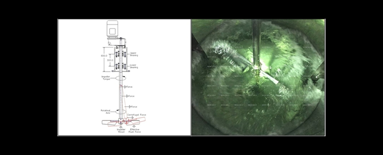
Impellers torque is the moment summation of horizontal components of the blade hydraulic force, For constant shaft speed and an axial-flow impeller fully submerge in liquid, the torque has a time average value and fluctuating value. This torque produces a steady and fluctuating shear stress in the shaft, Shaft stresses, along with the tensile stresses create by the shaft bending moments and axial thrust.
The shaft loads which originate from th mass of shaft and the impeller, There forces are either the centrifugal or gravity forces (weight of the shaft and impellers assembly). The centrifugal force are create when the impeller and shaft do nate rotate about the ratational axis determined by the bearing.
Note:
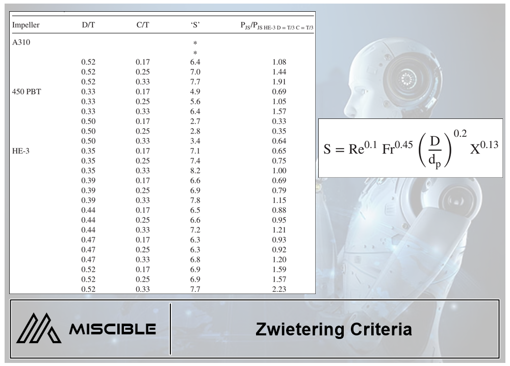
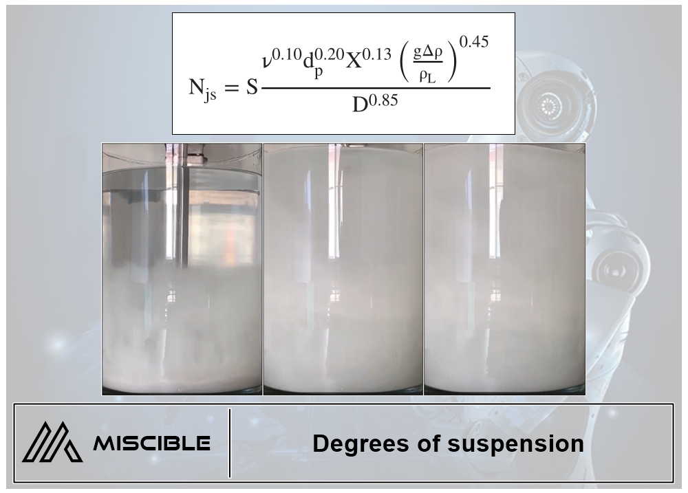
The impeller shaft loads are difficult to calculate using hydraulic principle, They are usually measured on a laboratory model and correlated with 'Dimensionless Number' such as Reybnolds Number / Force Number / Power Number and using similarity principles.
ทัศนะของ MISCIBLE
ใน EP แรกของ Coures-3 จะขอกล่าวถึงเรื่องทั่วไปของสิ่งที่ควรพิจารณาก่อนการออกแบบและคำนวณเพลาเพื่อปูทางก่อนครับ...ซึ่งขอแสดงทัศนะในฐานะผู้ออกแบบและผลิต Agitator ขายเท่านั้น และ ขอไม่แสดงทัศนะเชิงวิชาการมากเกินไปเพราะอยากแชร์ประสบการณ์จริงมากกว่า ส่วนของวิชาการก็หาอ่านกันเองได้ครับมีเยอะมาก,....ในฐานะผู้ออกแบบ การออกแบบ Agitator, เพลาเป็นสิ่งที่ผมให้ความสำคัญอันดับหนึ่ง เพราะหากเราออกแบบใบกวนดีแล้วตรงตาม Rheology แล้ว แต่ออกแบบเพลาไม่สอดคล้องกับการส่งกำลังของต้นกำลังและสอดคล้องแรงจากใบกวน ก็จะทำให้ Agitator นั้นเสียหายมาก
(1.)...สิ่งที่น่ากังวลมากที่สุดในการออกแบบ shaft of Agitator ไม่ใช่ขนาดของเพลา แต่คือ ความยาวของเพลาต่างหาก เพราะความยาวเพลาทำให้เกิด Bending Moment,Centrifugal Force และ Shaft Vibration ซึ่งส่งผลเสียหายโดยตรงกับ Agitator ทั้งหมด ต่อเนื่องไปยัง Sealing and Bearing
(2.)...แรงที่เกิดจากของเหลวเป็นสิ่งที่ยากจะคำนวณได้ ต้องใช้ประสบการณ์ในการเผื่อค่า Factor คำนวณเผื่อ
(3.)...กรณีลูกค้ามีงบประมาณจำกัด การเลือกใช้เพลาขนาดเล็กลงไม่เป็นผลดี ให้ใช้เพลาขนาดที่คำนวณได้และไปลด Cost ส่วนอื่นแทน เช่น Gear Motor, Housing เป็นต้น, การทำให้ Mixing Time นานขึ้น ยังดีกว่าลดขนาดเพลาแล้วทำให้ Agitator เสียหายทั้งชุด ซึ่งผมเองก็ใช้วิธีนี้กรณีลูกค้ามีงบจำกัด
(4.)...การ Run Agitator ตัวเปล่าโดยไม่มีของเหลวมีผลเสียมากอยู่เหมือนกันกรณีที่ใบกวนมีขนาดใหญ่ เพราะไม่มี Absorber ของ Centrifugal Force และ อีกทั้ง Impeller Thrust ยังช่วยรักษาสมดุลการแกว่งของเพลาได้อีกด้วย
(5.)...ผมไม่เคยเสี่ยงใช้ Dimensionless และ Similarity ในการ Scale Up ขนาดเพลาเลย ถึงแม้มันจะมีแนวโน้มว่าใช้ได้เพราะเป็นการ Scale Up ของ Solid ก็ตาม, ผมจะเลือกวิธีการคำนวณใหม่ตาม Loads จริงทุกครั้ง, การใช้ Dimensionless และ Similarity มีความเสี่ยงสูงในกรณีเพลาของ Scale Up ที่มีความยาวมาก
ขอบคุณครับ
สถาพร เลี้ยงศิริกูล (Agitator Designer)
MISCIBLE TECHNOLOGY CO., LTD
Tel: 02.548.0414-5 / 091.7400.555
Line : @agitator
www.miscible.co.th